Tag: iNoPhone
iNoPhone Update
by james on Feb.28, 2010, under iNoPhone
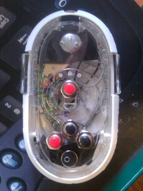
So I decided to get smaller buttons for my iNoPhone. I had to unsolder the old buttons which wasn’t hard. The new buttons are smaller in diameter so it was harder to get them secured to the plastic face. There’s a blurry Katrina in the background.

I tested all the buttons and they seem to work. It’s a lot lower profile. If you lay it like it originally would be it looks almost like a regular mouse. I almost got some really small tactile switches, but I thought they might be too short.

The latest fashions!

It’s almost the same size as my HTC Hero.

A comparison with Katrina, she’s a pretty big cat though!
Other updates on first post:
Charging works, I’ve done it a couple times now. The speaker/mic aren’t the best, but I think I just need more holes in the face plate.
iNoPhone2
by james on Nov.27, 2009, under iNoPhone
My wonderful cat Perry decided to chew up a bluetooth headset (Jabra BT5020). I’ve seen before the iNoPhone which is totally awesome! I decided to rip it all the way apart and make my own iNoPhone from a spare Apple mouse that I had.
It wasn’t too hard after I figured out what wire to use. At first I tried 22 or 24 gauge wire. It worked, but the wires were stiff and it was hard to solder onto the tiny switches. Also, I pulled a trace off so I decided that it wasn’t going to work. I previously cut up an IDE cable to wire an SD card in my WRT54GL. There was plenty of spare ribbon to go into this project as well.
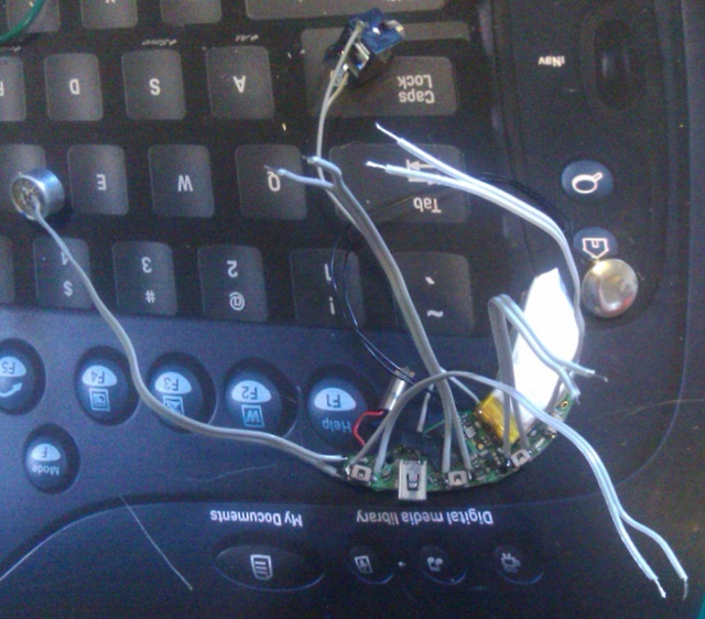
On top of pulling a trace off, I broke the wire for the mic. One problem with the design of the iNoPhone was charging. So I used a headphone jack and drilled out the normal cable hole to accommodate. This was awesome till I pulled the single trace I had found that went to the +5V on the USB. After a lot more searching I gave up cause the 22 gauge wire was too big to solder to the tiny _8_ pins for the USB on the board.
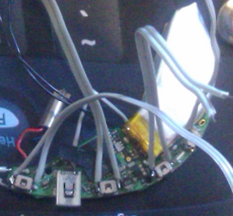
In comes the IDE ribbon cable. Definitely small enough to solder to the USB pin and alot easier to solder to the pins of the switches. Now I was having problems with the mic. I just couldn’t get it soldered well. I needed a couple more hands, but I didn’t have them so I did the next best. I pulled out the mic from an old “desktop mic” I had around. Plenty of room to solder!
As above I wired in a headphone jack to charge the unit. Then I cut the end off a USB cable and soldered a male stereo plug on. Now if I only had smaller buttons it would look pretty awesome.
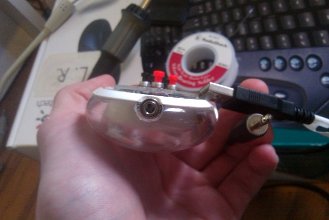
I haven’t been able to verify that charging works. The LED is not the right color when it’s supposed to be charging. I did get my multimeter out and checked the voltage on the battery, 3.86V without charger, 3.96V with charger. So, I think it works.
I will close with thanks to Mark from geektechnique.org I probably would have never thought of this without first seeing his iNoPhone.
I never knew you, but R.I.P. Mark